|
|
Marine &
Industrial Applications |
 Rubber Joints Rubber Joints |
|
|
Rubber Joints
Product Information Page
Vibration - Noise -
Shock - Movement
Apollo
rubber spool-style expansion joints are available in a wide variety of
elastomers, sizes configurations, and working pressures. For example,
neoprene is supplied where conformance to U.S. Coast Guard requirement
46FR-5660-25(e) is necessary. Viton is available for high temperatures.
Natural rubber, PTFE, and other compounds can be furnished for special
requirements. Standard flange drilling 150# ASA - others available.
See below for movements and working pressures. |
| |
|
|
|
|
|
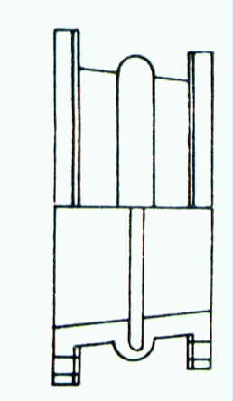
STYLE 120 - Reducing
Expansion Joint- concentric or
eccentric
|
Designed to connect
piping of unequal dimensions, otherwise same as Style 67 below. Concentric
expansion joints have the axis of each end concentric with the other;
eccentric joints have the axis of each end offset from the other. |
| |
|
|
|
|
|
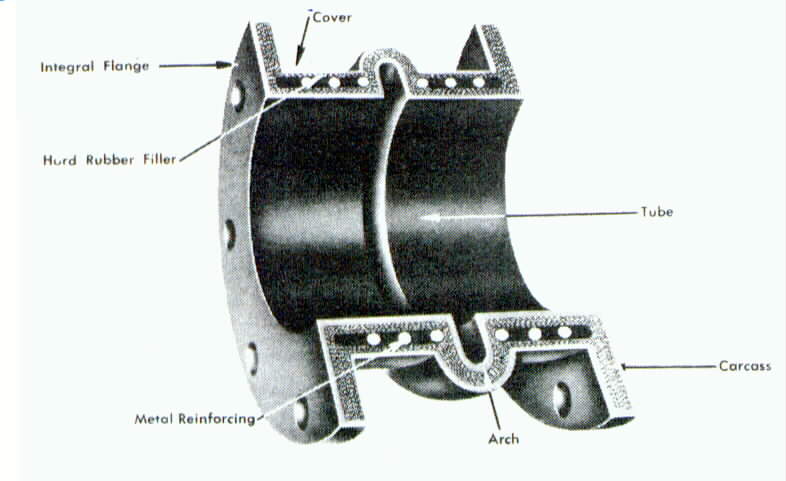
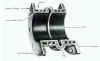
STYLE 67 - Single or Double Arch Click to
enlage.
|
Designed to connect
piping of equal diameters for the elimination of vibration, stress and
noise. Style 67 is normally supplied with a single unfilled arch which is
suitable for most standard applications. Double or triple arches are
offered to accommodate movements greater than those which a single arch is
capable of. Filled arches can be specified for slurry service or to reduce
turbulence. Style
67 expansion joints are suitable for full vacuum service. |
| |
|
DIMENSIONS FOR SINGLE
ARCH
EXPANSION JOINT STYLE 67
| Joint
SIze I.D. (in.) |
Recommended
Face to Face (in.) |
Max
Working Pressure (PSI) |
Flange
O.D. (in.) |
Bolt
Circle diam. (in.) |
Bolt
Holes |
Ring
I.D. (in.) |
Dimensions |
| Number |
Diam.
(in.) |
A |
B |
C |
D |
E |
| 4 |
6 |
165 |
9 |
7
1/2 |
8 |
3/4 |
5
7/8 |
|
|
|
|
|
| 5 |
6 |
140 |
10 |
8
1/2 |
8 |
7/8 |
6
7/8 |
|
|
|
|
|
| 6 |
6 |
140 |
11 |
9
1/2 |
8 |
7/8 |
7
7/8 |
|
|
|
|
|
| 8 |
6 |
140 |
13
1/2 |
11
3/4 |
8 |
7/8 |
9
7/8 |
|
|
|
|
|
| 10 |
8 |
140 |
16 |
14
1/4 |
12 |
1 |
12
1/8 |
|
|
|
|
|
| 12 |
8 |
140 |
19 |
17 |
12 |
1 |
14
1/2 |
|
|
|
|
|
| 14 |
8 |
85 |
21 |
18
3/4 |
12 |
1
1/8 |
16
1/2 |
|
|
|
|
|
| 16 |
8 |
65 |
23
1/2 |
21
1/4 |
16 |
1
1/8 |
18
1/2 |
|
|
|
|
|
| 18 |
8 |
65 |
25 |
22
3/4 |
16 |
1
1/4 |
20
1/2 |
|
|
|
|
|
| 20 |
8 |
65 |
27
1/2 |
25 |
20 |
1
1/4 |
22
5/8 |
|
|
|
|
|
| 22 |
10 |
65 |
19
1/2 |
27
1/4 |
20 |
1
3/8 |
24
5/8 |
|
|
|
|
|
| 24 |
10 |
65 |
32 |
29
1/2 |
20 |
1
3/8 |
26
5/8 |
|
|
|
|
|
| 26 |
10 |
55 |
34
1/4 |
31
3/4 |
24 |
1
3/8 |
28
7/8 |
|
|
|
|
|
| 28 |
10 |
55 |
36
1/2 |
34 |
28 |
1
3/8 |
30
7/8 |
|
|
|
|
|
| 30 |
10 |
55 |
38
3/4 |
36 |
28 |
1
3/8 |
32
7/8 |
|
|
|
|
|
|
| |
|
|
|
| |
|
|
|
|
|
STYLE 61 - Pipezorber

|
Style 61 is a rubber
pipe with a smooth, abrasion-resistant rubber lining used to
substantially reduce noise and vibration in rigid metal pipe systems.
APOLLO can design a complete custom system using straight units, bends,
and tapers.
Style 61-1
is available for service to 150 PSI.
Style 61-2
can be used up to 250 PSI. |
| |
|
PIPEZORBER DATA
| Size
I.D. inches |
Length
Inches |
Extension
Inches |
Compression
Inches |
Transverse
Inches |
Working
Pressure |
Temp
- F?/font> |
Style
61-1 |
Style
61-2 |
Class
I STD |
Class
II HT |
| 2 |
12 |
3/8 |
1/4 |
3/8 |
150 |
250 |
180 |
250 |
| 2
1/2 |
12 |
3/8 |
3/8 |
3/8 |
150 |
250 |
180 |
250 |
| 3 |
18 |
3/8 |
3/8 |
3/8 |
150 |
250 |
180 |
250 |
| 4 |
18 |
1/2 |
3/8 |
3/8 |
150 |
250 |
180 |
250 |
| 5 |
24 |
1/2 |
5/8 |
3/8 |
150 |
250 |
180 |
250 |
| 6 |
24 |
1/2 |
5/8 |
3/8 |
150 |
250 |
180 |
250 |
| 8 |
24 |
1/2 |
3/4 |
3/8 |
150 |
250 |
180 |
250 |
| 10 |
24 |
1/2 |
3/4 |
3/8 |
150 |
250 |
180 |
250 |
| 12 |
24 |
1/2 |
3/4 |
3/8 |
150 |
250 |
180 |
250 |
|
| |
|
|
|
| |
|
|
|
|
|
|
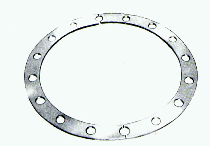
Retaining
Rings & Control Rods
Galvanized steel
retaining rings are used with all expansion joints having integral rubber
flanges. They provide a metal backup ring behind the rubber flange which
forms a seal when the bolts re tightened. The rings are split to
facilitate easy installation. One set, consisting of rings, is optional
with each flanged unit. Steel washers should be inserted at the bolt holes
where the rings are split. The retaining rings are split into two segments
in sizes up to 10"; four segments in sizes up to 24". All rubber
expansion joints and pipezorbers installed in piping MUST BE rigidly
anchored on both sides of the joint or connector. The anchoring must be
capable of withstanding the line thrusts generated by the internal
pressure or wide temperature fluctuations. If it is not practical to
install anchors, control rods must be ordered. |
|
|
|
|
|
|
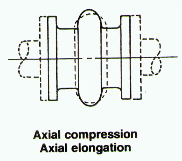
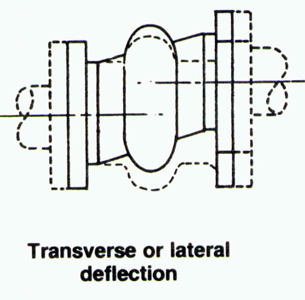
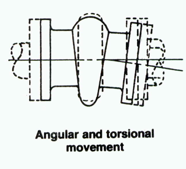
Types of Movement |
|
|
 |
|


 New
York: 718-273-7300
New
York: 718-273-7300